What Is an Inline Flow Meter and How Does It Work?

An Inline Flow Meter measures fluid moving through a pipe without requiring a separate open channel. Installed directly in the line, it can provide continuous readings for water, chemicals, fuels, air, or other compatible fluids. The exact operating principle depends on the meter design. Some models use electromagnetic induction; others measure turbine rotation, pressure differences, or ultrasonic signals.

R. W. Miller, author of Flow Measurement Engineering Handbook, is a recognized authority in flow measurement. His work highlights a practical lesson: meter selection depends on the fluid, operating conditions, and installation—not just the pipe size. That distinction matters. A meter chosen from a catalog alone may give unreliable readings if the liquid is viscous, the pipe is partly filled, or the flow is turbulent.

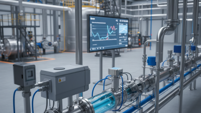
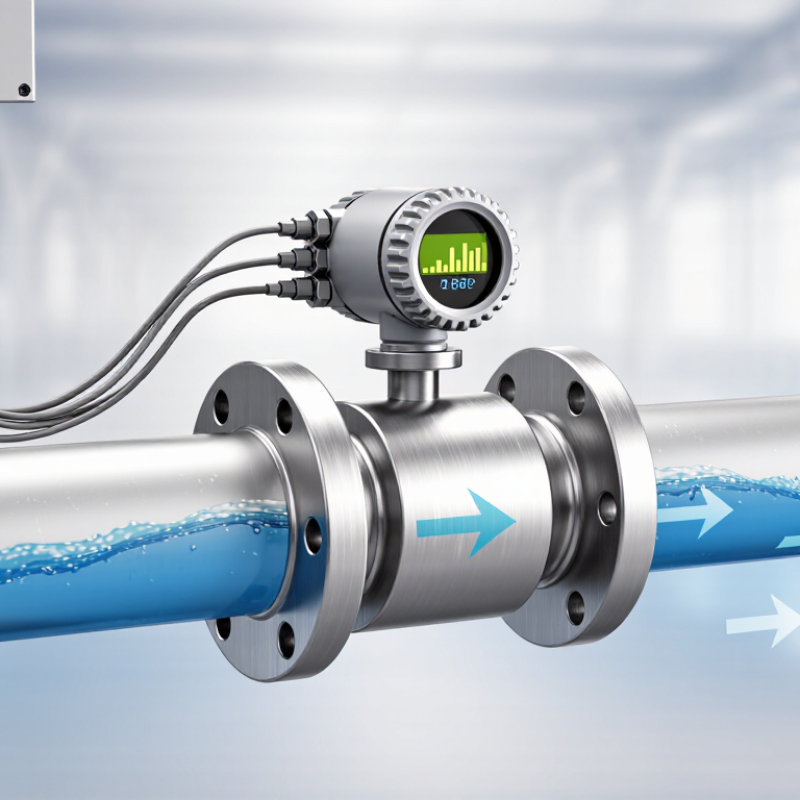
Picture a meter installed between two flanges, with a display showing flow rate as the process runs. Inside, a sensor detects a physical change caused by moving fluid, then converts that signal into a readable measurement. Some devices also totalize volume or transmit readings to a control system. Simple to picture. Not always simple to specify.

This introduction explores what an Inline Flow Meter is, how its main designs work, and which factors affect measurement accuracy. It also considers installation and maintenance, where small details—such as straight-pipe length or sensor alignment—can matter. No meter suits every process. Understanding its limits is part of using it well.
What Is an Inline Flow Meter and How Does It Work?

What an Inline Flow Meter Is

What an Inline Flow Meter Is

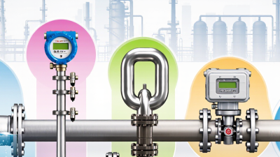
An inline flow meter is installed directly in a pipe to measure how much fluid passes through it. The meter’s sensing element contacts the flow or measures it through the meter body. Depending on its design, it can report volume per minute or mass per second. Common types include electromagnetic, turbine, Coriolis, and differential-pressure meters. Each suits different fluids and operating conditions.

Placement matters. A meter may need straight pipe upstream and downstream to produce reliable readings. ISO 5167, for example, specifies conditions for measuring flow with orifice plates, nozzles, and Venturi tubes in full pipes. The right choice depends on factors such as fluid conductivity, cleanliness, pressure, and temperature. A meter selected without checking these details can give misleading results.

Flow data can help operators spot changes in a process or assess pump performance. The U.S. Department of Energy’s Improving Pumping System Performance sourcebook reports that pumping systems use nearly 20% of the world’s electricity demand and 25–50% of energy in some industrial plants. A meter does not reduce energy use by itself. It gives operators measurements they can use to investigate. Even a well-installed meter can disappoint if it is poorly calibrated.

Key Components of an Inline Flow Meter

Key Components of an Inline Flow Meter

An inline flow meter has a body installed directly into a pipe, so fluid passes through its measuring section. The body must withstand operating pressure and suit the fluid’s temperature and chemistry. Inside, a sensing element detects flow, but its design depends on the measurement method. A turbine meter uses a rotor that turns as fluid moves past it. An electromagnetic meter uses electrodes to detect voltage in conductive liquids. Ultrasonic models use transducers to send and receive sound signals through the flow. Different principles suit different fluids. No single sensor fits every job.

The meter’s electronics convert sensor signals into a flow rate, then send readings to a display or control system. Some models also store totals or report diagnostic information. Seals and process connections matter, too: a poorly matched gasket can leak, while incorrect installation may distort readings. In field setups, nearby pumps, elbows, and partially filled pipes can complicate measurement. Follow the meter’s installation guidance, including any required straight pipe lengths. Small details count. Still, a clean display does not prove the reading is accurate; compare it with operating conditions and check for buildup or wear during maintenance.

What Is an Inline Flow Meter and How Does It Work? — Key Components of an Inline Flow Meter
Component What It Does How It Works Common Examples or Notes
Meter body or flow tube Provides the section of pipe through which the measured fluid passes. Is installed in the pipeline so the fluid flows through a defined measurement area. Materials and lining are selected to suit the fluid, pressure, temperature, and corrosion conditions.
Primary sensing element Responds to a physical property of the flow and provides the basis for measurement. Detects effects such as fluid velocity, pressure difference, or electromagnetic induction. The design depends on the meter type; there is no single sensing element used in every inline flow meter.
Electrodes Pick up a voltage generated by a conductive liquid moving through a magnetic field. Used in electromagnetic meters, where the measured voltage is related to the liquid’s average velocity. Magnetic flow meters require a sufficiently conductive liquid and are generally unsuitable for nonconductive fluids such as most oils and gases.
Ultrasonic transducers Send and receive sound signals used to determine flow velocity. Transit-time designs compare upstream and downstream signal travel times; Doppler designs use frequency shifts from sound reflected by particles or bubbles. Which method is suitable depends on the fluid and its acoustic properties.
Rotor or turbine assembly Converts moving fluid into rotational motion that can be sensed. In a turbine meter, rotor speed is related to fluid velocity over the meter’s calibrated operating range. Moving parts can be affected by wear, contamination, or changes in fluid properties.
Primary restriction and pressure taps Create and measure a pressure difference associated with flow. In differential-pressure meters, a restriction such as an orifice plate causes a pressure drop that is used to calculate flow. The calculation also depends on factors such as fluid density, meter geometry, and operating conditions.
Transmitter or signal processor Converts sensor signals into a usable flow measurement. Applies the meter’s measurement relationship and configuration to produce a flow-rate signal. Depending on the design, it may be built into the meter or installed separately.
Display and output connections Present measurements locally or send them to monitoring and control equipment. May show flow rate or accumulated volume and provide electrical or digital outputs. Available outputs and display features vary by meter; they are not present on every model.
Seals and electrical connections Help maintain the pressure boundary and protect signal connections. Seals limit leakage at wetted joints, while electrical enclosures and cable entries protect connections as specified for the installation. Compatibility and enclosure protection should be checked against the fluid, pressure, temperature, and site conditions.

How an Inline Flow Meter Measures Flow

An inline flow meter sits directly inside a pipe, where fluid passes through its measuring section. How it measures depends on its design. Some meters detect fluid speed and use the pipe’s known cross-sectional area to calculate flow volume. Others measure pressure differences or count fixed volumes as they move through the meter.

For example, an electromagnetic meter senses voltage produced as conductive liquid moves through a magnetic field. A turbine meter uses a rotor; faster flow makes it spin faster. The meter converts that motion into a reading, often in liters per minute or cubic meters per hour. It sounds simple. It isn’t always.

The displayed value is only useful when the meter suits the fluid and installation. Bubbles, changing viscosity, or a partly filled pipe can affect readings. Straight pipe before and after the meter may also be needed to steady the flow. In practice, technicians check the meter’s range, fluid compatibility, and calibration conditions. That distinction is easy to overlook: a meter measures a signal, then uses that signal to estimate flow.

Common Types of Inline Flow Meters

What Is an Inline Flow Meter and How Does It Work?

Common Types of Inline Flow Meters

An inline flow meter sits directly in a pipe and measures fluid moving through it. Its sensing method depends on the meter design. Turbine meters use a rotating rotor; faster flow makes it spin faster. Electromagnetic meters detect voltage in conductive liquids, so they are unsuitable for oils and many gases. Ultrasonic meters use sound waves and can measure flow without placing moving parts in the stream. That matters. Differential-pressure meters infer flow from a pressure change across a restriction, while Coriolis meters measure mass flow through vibrating tubes.

Each type has trade-offs. Turbine meters can suit clean, steady liquids, but particles may wear the rotor. Electromagnetic models handle many conductive liquids, though pipe grounding and full-pipe conditions matter. Ultrasonic readings can be affected by bubbles, pipe material, and installation quality. Coriolis meters offer direct mass-flow measurement, but their cost and pressure drop may be higher. No option is perfect. Choosing from a fluid name alone is a common mistake; viscosity, temperature, flow range, and maintenance access also deserve review.

Tips: Check the meter’s specified fluid range and required straight pipe length before installation. Confirm readings against a known operating condition after setup. If measurements drift, inspect for air, deposits, or changing process conditions before assuming the meter has failed.

Where Inline Flow Meters Are Used

Where Inline Flow Meters Are Used

Inline flow meters are used wherever operators need to measure fluid moving through a pipe. In building systems, they help monitor chilled water, hot water, and heating loops. A technician may compare readings across a pump or check whether a branch receives enough flow. Small differences matter. In water treatment plants, meters track flow through filtration and distribution stages. Manufacturing facilities use them to monitor cooling water, cleaning solutions, and other process fluids.

The right location depends on the fluid, pipe size, and operating conditions. A meter designed for clean water may not suit a liquid containing suspended particles. Temperature, pressure, and pipe layout also affect performance. Installers should follow the meter’s instructions for orientation and straight pipe runs. Crowded mechanical rooms can make this difficult, and a neat-looking installation is not always an accurate one. That deserves a second look.

Tips: Confirm fluid compatibility before installation. Check the reading against a known operating condition, then recheck it after the system stabilizes. Keep the sensor accessible for inspection. A little planning helps avoid awkward maintenance later.

What Is an Inline Flow Meter and How Does It Work? — Where Inline Flow Meters Are Used

An inline flow meter is installed directly in a pipe to measure the flow of a liquid or gas. The chart converts example flow rates from cubic metres per hour to litres per minute using the exact relationship 1 m³/h = 16.67 L/min.

Inline flow meters are used in water and wastewater systems, HVAC, industrial process lines, and food and beverage production. The appropriate meter depends on the fluid, flow range, pipe, and operating conditions.